A while ago my mom saw a clock where the time was shown using only words instead of numbers:

If you speak spanish, you can see that there are letters spelling every possible combination of times. You could show any time of day provided you light the correct LED combination (well, technically not every possible combination is available as the time is rounded up to intervals of 5 minutes, so 10:57 would be displayed as “five to eleven”).
Disclaimer: I’ve been approached by the people at PCBWay to review their PCB Prototyping product. They gave me a coupon to try the service out for free in exchange for a review. So this is not a sponsored ad or anything like that. They never prompted me to say anything in particular; these are my own words.
My mom looked for a clock like this and quickly found that they ran for over $200, which is insane! I told her that I could make one for under $20 and thus the journey began.
Arduino Prototype
The first thing I needed was an LED matrix which I made by soldering some addressable LED “pixels” I found on Amazon:


I cut a small plywood square from a scrap piece that I had, drilled and countersunk some holes. Then I hot-glued all the LEDs in place and pre-tinned each solder pad. Then soldering began. This took A LOT of time!


After making sure all LEDs were working, I made a test sheet in illustrator with the letters in places, and cut it in the vinyl cutter using some thick cardstock. Remember, this is just the beta version. The final version will have a way nicer look!


After cutting the black vinyl template, I applied it over a piece of acrylic, and added a white sheet of paper behind it to act as a diffuser. Then, I went into the shop and made a quick and dirty frame for the whole assembly. It looks like this:

Since I didn’t have any buttons at hand, I decided to use capacitive touch buttons instead using some bolts. They look like this:


But let’s be honest. The prototype circuit looks pretty awful. We can do better! Let’s make a PCB!
The PCB
The cool think about this PCB is that it doesn’t really DO anything. It’s just a bunch of connectors taking signals from here to there. Other than a pretty sizable capacitor to prevent the Arduino from rebooting if I set all the LEDs to white (too much power), the whole thing is pretty straight forward:


I went to the PCBWay website and I uploaded my board to their platform. There are a lot of options to chose but set everything to the default, except that I chose the white colour for the PCBs. The 80s called and they want their green coloured PCBs back!

A cool thing they do is that if you choose a white solder mask, they automatically change the silk screen to black just so that your silk screen doesn’t get lost in the background.
I did have some trouble entering my shipping address in Canada because their system was confusing city and province names, but that seems to be fixed now.
After uploading, their system sets the order on hold until approval (which took less than 24 hours). And after that, the order changed status pretty fast and I could see what they were actually doing. This can be seen in their order status page:

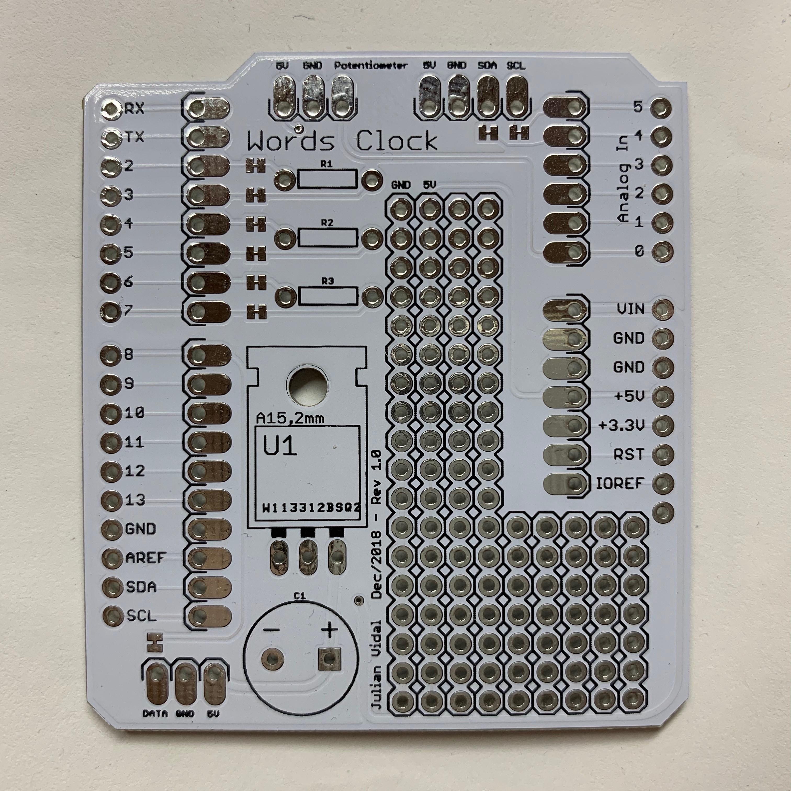
3 days after the last status change I had the PCBs in my hand and they looked spiffy! I love white PCBs!


All the solder pads looked great and all the boards that I assembled worked perfectly. Here are a couple of shots of one of the assembled boards. Note that I soldered the capacitor sideways so that it fit in the particular tight enclosure I was working with.


Did you spot the boo-boo? :) Here’s a close-up:

Yes. I screwed up! I usually use the Eagle auto-router and just go with what it gives me. This time I routed the whole board by hand. Doing it this way makes for a much cleaner board and I learned a lot… but… I got so caught trying to make the board look nice that I accidentally swapped the 5V and GND pads! Oh, well…
I’m super happy with the PCBWay service. There were no complications, no delays, and everything worked exactly as I expected. The quality of the silk screen in particular is the best that I’ve seen so far. On other PCB services that I used sometimes the silk screen chips off (in minuscule bits) but this one is perfect all the way.
Conclusion
I love Arduino, but hate breadboards. Everything is so flimsy and when you eventually want to take the prototype to vero board or any of the more permanent alternatives, it takes forever to do so and it’s an incredibly error prone process. Making a PCB leaves everything clean and repeatable. The next time your friend comes to your house you can snap one of these PCB shields on top of an Arduino, load up the software and you are ready to go!
Leave a Reply