Tag: led
-
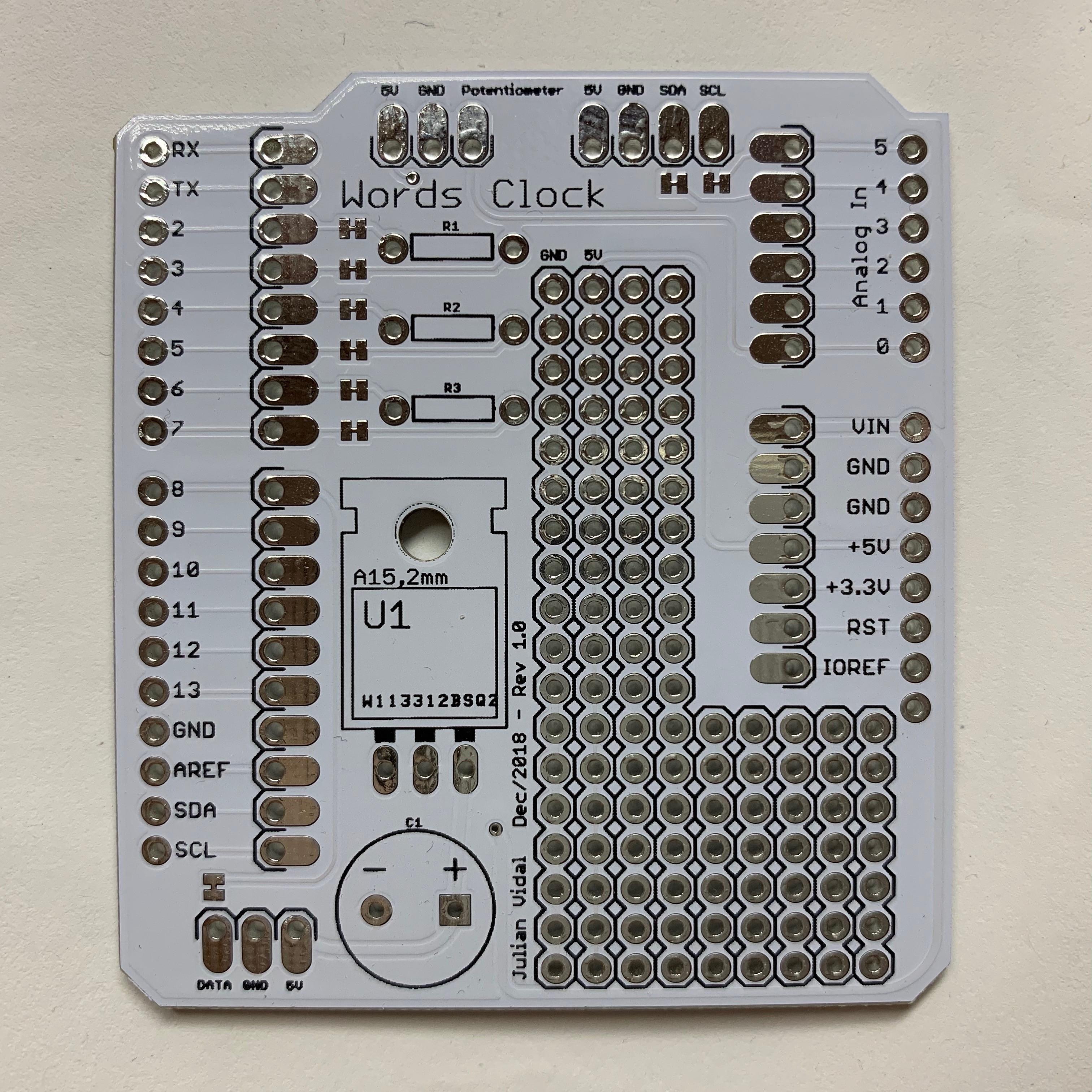
PCBWay PCB Prototyping review (aka how I made an LED word clock)
A while ago my mom saw a clock where the time was shown using only words instead of numbers: If you speak spanish, you can see that there are letters spelling every possible combination of times. You could show any time of day provided you light the correct LED combination (well, technically not every possible…
-
Seeed Studio’s Fusion PCB review
Today I’ll be reviewing a new PCB service from Seeed Studio called Fusion PCB. For that I will be making a simple acrylic LED display. Let’s see how it goes… Disclaimer: I’ve been approached by the people at Seeed to review their Fusion PCB product. They gave me a coupon to try the service out…
-
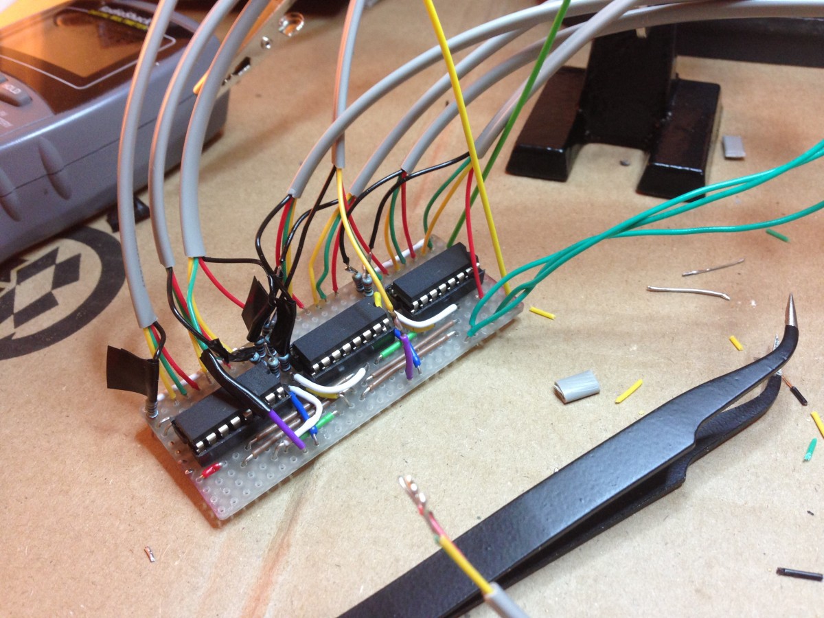
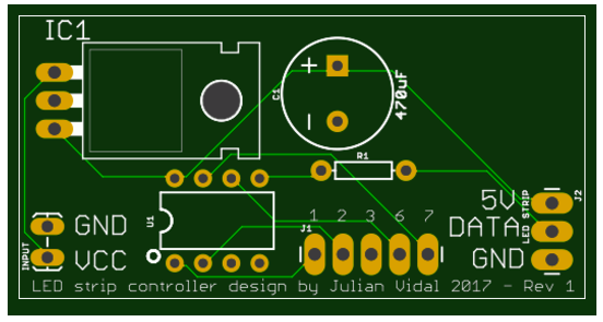
8 RGB LED Controller
UPDATE: I’ve now made a custom PCB out of this. This is my first experiment with Arduino. Like most people starting out with Arduino, I wanted to make stuff blink! So after finishing up the Arduino Starter Project Book I started hooking up LEDs to my Uno’s outputs. I very quickly ran out of outputs…