Tag: arduino
-
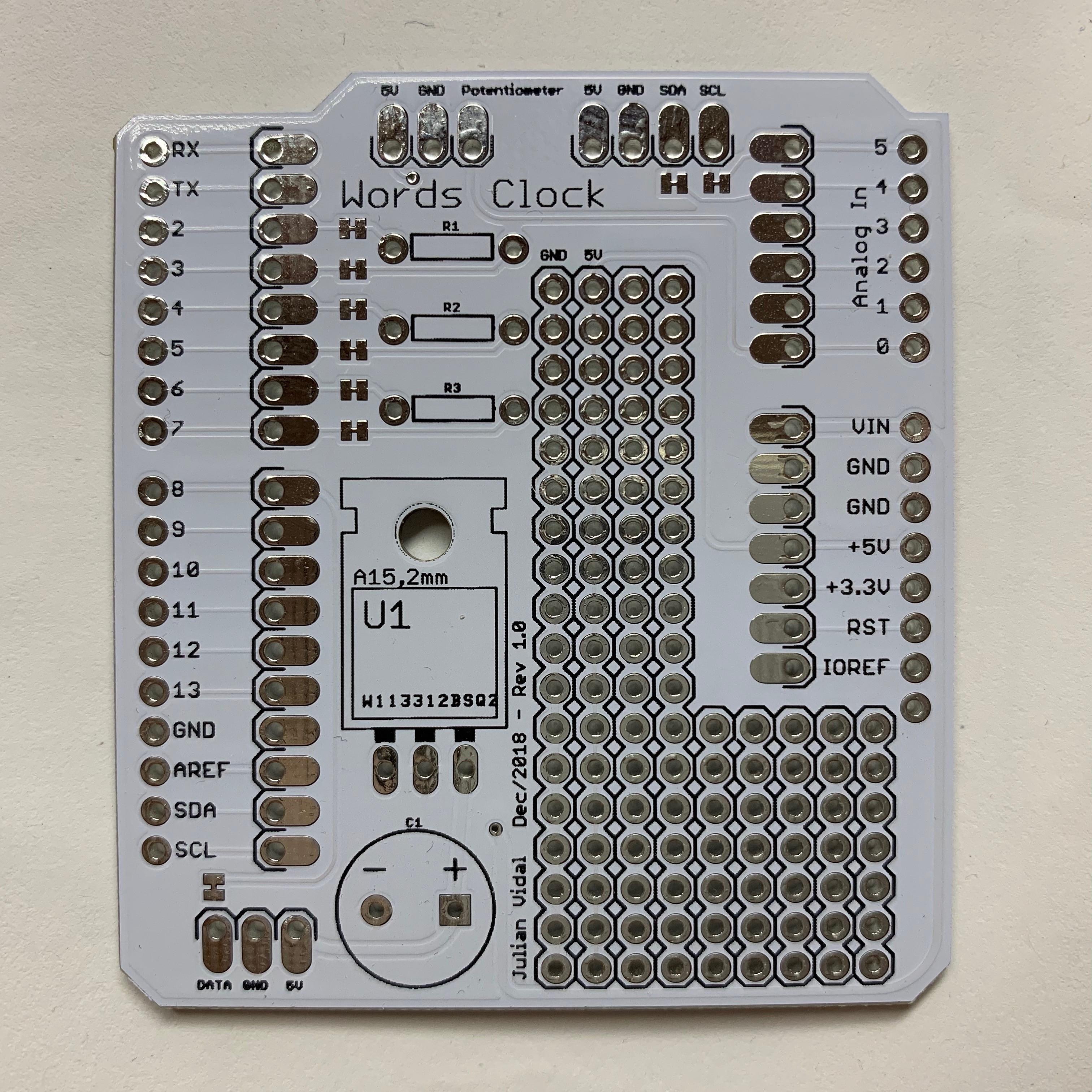
PCBWay PCB Prototyping review (aka how I made an LED word clock)
A while ago my mom saw a clock where the time was shown using only words instead of numbers: If you speak spanish, you can see that there are letters spelling every possible combination of times. You could show any time of day provided you light the correct LED combination (well, technically not every possible…
-
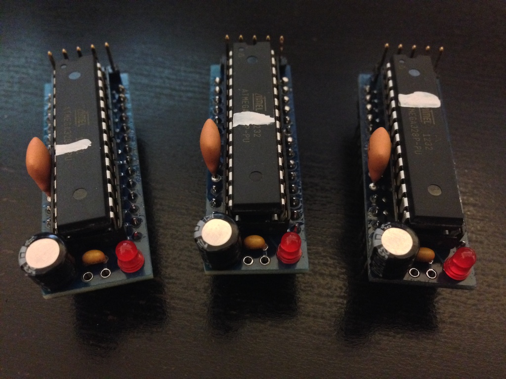
How to program a Dorkboard with an FTDI breakout
I’ve been playing with my Arduino long enough to realize that it is much cheaper to maker my own breadboard Arduino and transfer that into either a PCB or Veroboard than to actually buy a full Arduino for every little thing I make. In order to program my breadboard Arduino I’m using Sparkfun’s FTDI Basic…
-
Calibrator: An Arduino library to calibrate sensors hooked to analog inputs
Once you get past your first few projects with the Arduino, you soon realize that the calibration method they show on their webpage is just a sample and cannot be used with many sensors without polluting your code with a ton of variables. So, here it is. My own take on sensor calibration library. You…
-
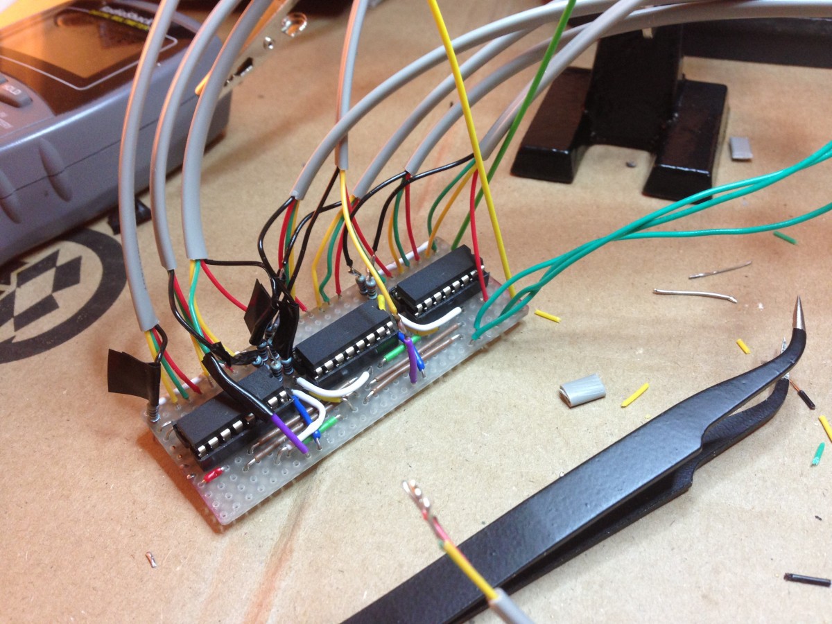
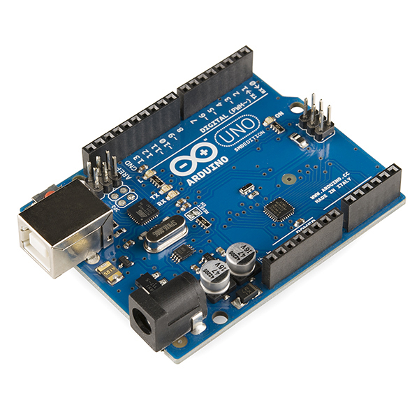
8 RGB LED Controller
UPDATE: I’ve now made a custom PCB out of this. This is my first experiment with Arduino. Like most people starting out with Arduino, I wanted to make stuff blink! So after finishing up the Arduino Starter Project Book I started hooking up LEDs to my Uno’s outputs. I very quickly ran out of outputs…