Category: Featured
-
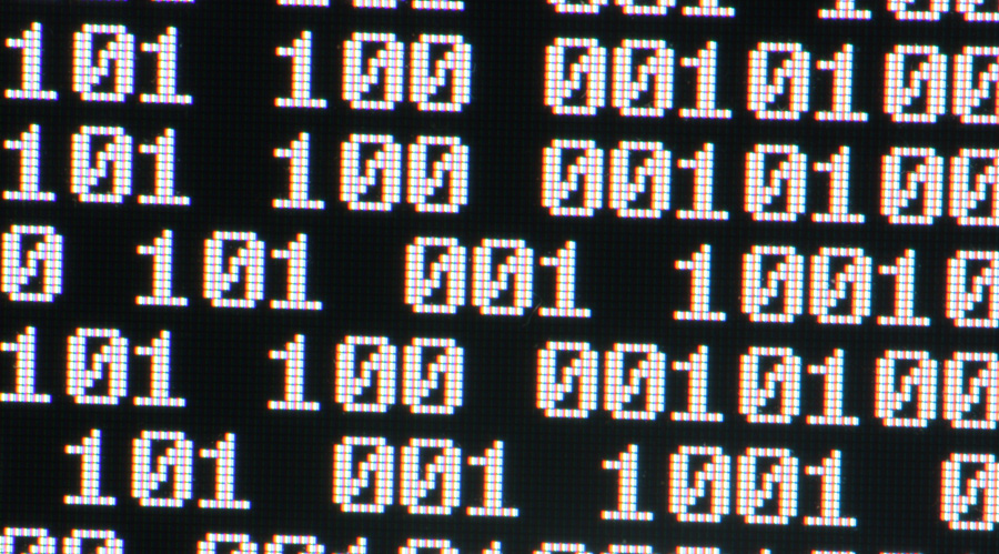
Learn how to read and write binary numbers in 5 minutes.
Over the years I’ve been asked to explain this to many people and most of the times as I was done explaining this, people would say “Huh, I thought it was harder!”. I think the reason is that when people are taught how to do this they are shown the math behind it and they…
-
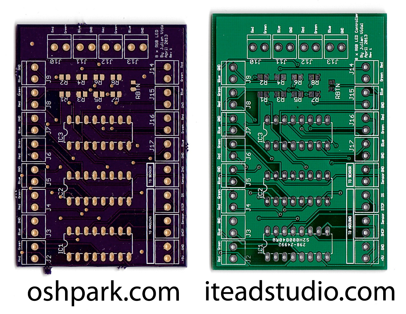
PCB Comparison: OSH Park vs. iTeadStudio
I took my 8 RGB LED Controller prototype and decided to try to make a PCB of it (my first attempt at a PCB, that is). Most people at the Arduino forums had recommended I do this in EAGLE but they warned me that the learning curve was steep. So I tried doing it in…
-
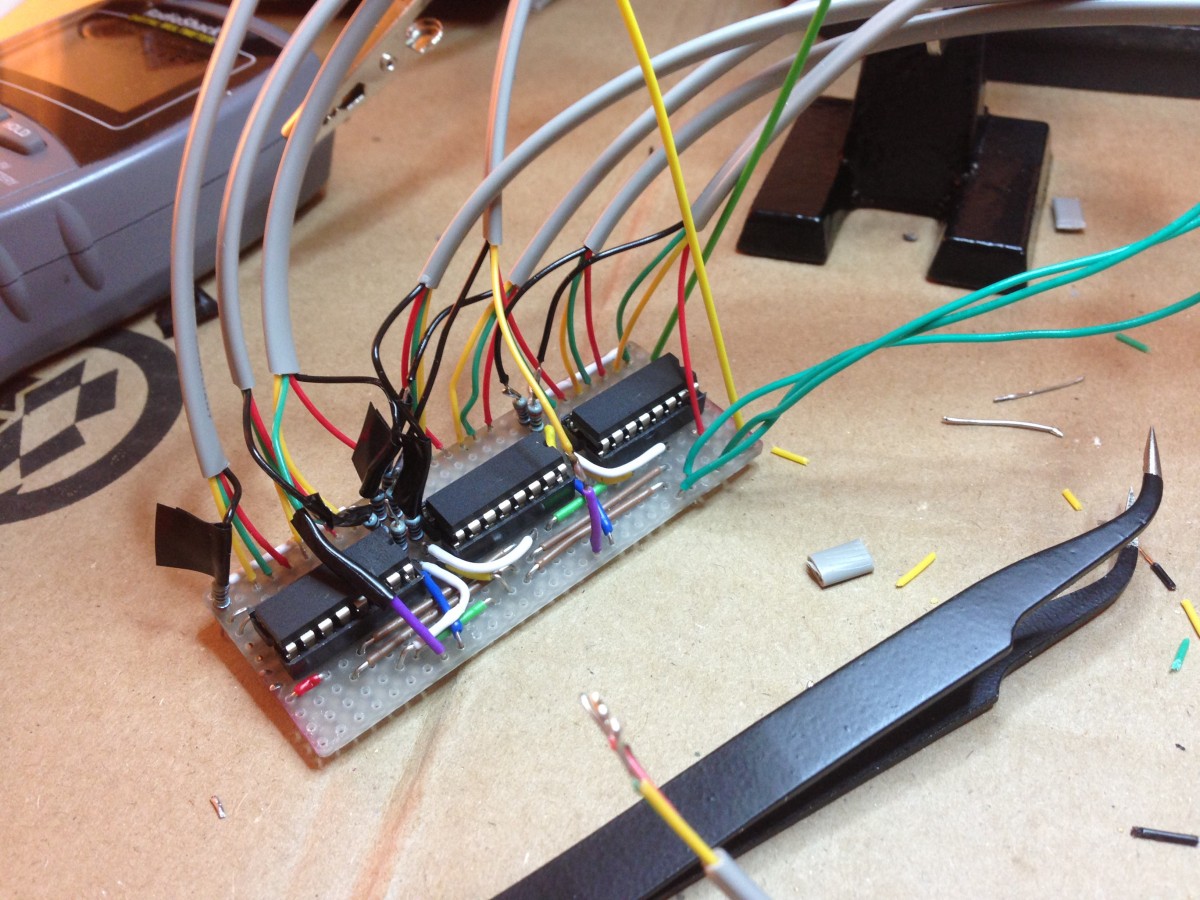
8 RGB LED Controller
UPDATE: I’ve now made a custom PCB out of this. This is my first experiment with Arduino. Like most people starting out with Arduino, I wanted to make stuff blink! So after finishing up the Arduino Starter Project Book I started hooking up LEDs to my Uno’s outputs. I very quickly ran out of outputs…