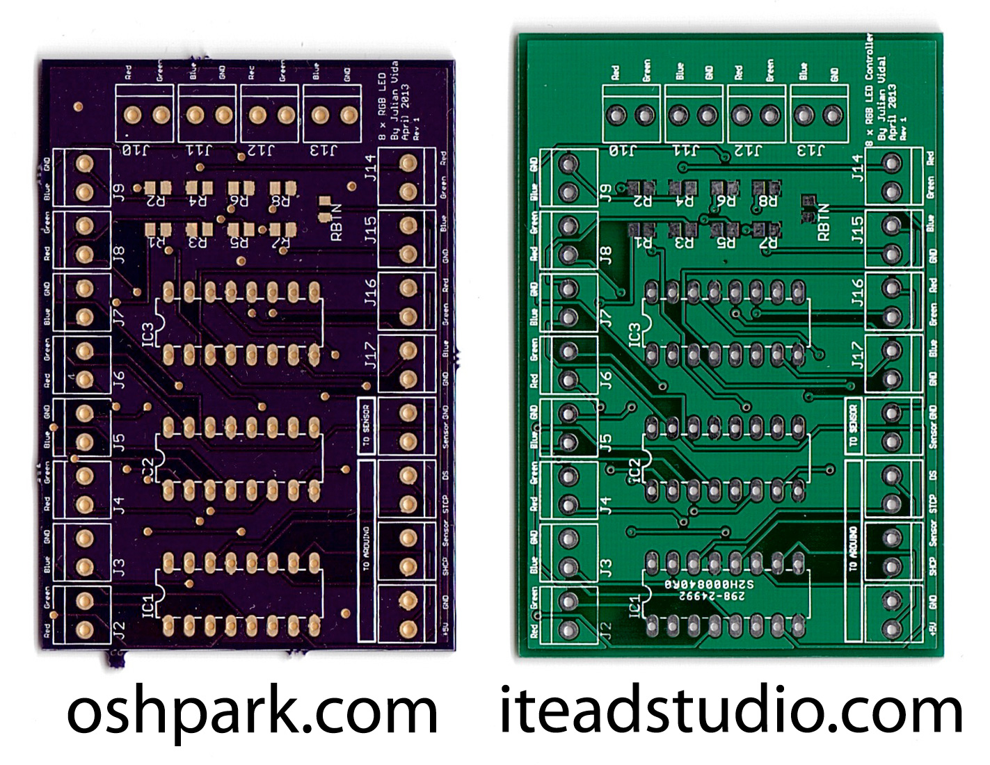
PCB Comparison: OSH Park vs. iTeadStudio

I took my 8 RGB LED Controller prototype and decided to try to make a PCB of it (my first attempt at a PCB, that is).

Most people at the Arduino forums had recommended I do this in EAGLE but they warned me that the learning curve was steep. So I tried doing it in Fritzing and failed miserably; couldn’t get the damn thing to do what I wanted. Then I gave EAGLE a try and thanks to Jeremy Blum’s tutorials could get a nice schematic done:

8 RGB LED Controller EAGLE schematic

Holy crap, that took me forever to do. When they say that EAGLE’s learning curve is steep they meant to say really f$#*@ing steep.

But the schematic is half the battle. After that you have to create the actual board layout which, again, took me forever to do. After many hours of getting cryptic errors and solving them by reading random forums, I got this:

8 RGB LED Controller EAGLE PCB

So far so good. Now I had to send them out to get printed.

A lot of people recommended iTeadStudio (a Chinese PCB manufacturer) and some other recommended OSH Park (US based), so I ordered a set of PCBs of each well aware that my design could easily be flawed and end up with a bunch of duds. For the same money OSH Park gives you 3 boards and iTeadStudio gives you 10. I was very curious to see what the quality difference was.

Note: A week after sending my order to iTeadStudio they wrote back saying that my design was 2mm over the limits of my chosen PCB size and they put my order on hold until I sent them the mind boggling amount of $2.90 extra. Yes, they put the order on hold for less than $3!

Three weeks later both orders arrived just a couple days apart. And this is what I got:

OSH Park vs iTeadStudio

Even to the untrained eye (like mine) there are a few differences worth noting. Both providers happily ignored the boundaries I set on my PCB. Note that the word “Controller” is cutoff on both boards (top right). You might be going back to the EAGLE board screenshot above and seeing that there is no word “Controller” there and you’d be right; I took that screenshot a few minutes ago from a more recent version of the board, but trust me, that word was well withing the boundaries of the board. Also note how iTeadStudio’s is much taller and also better trimmed while OSH Park’s is shorter and you can clearly see the marks where they cut the PCB off the neighboring boards.
Another thing to note is that OSH Parks’ board has “golden” pads while iTeadStudio’s has silver pads. I have no idea (and don’t really care) what the material is but the only thing I can say is that the OSH Park board required much less heat for the solder to “attach” to the pads so I guess it was easier to work with. The overall glossy purple finish looks way cooler too.
A funny thing on iTeadStudio: I paid for 10 boards but they’ve sent me 13. After reading around a bit I learned that this is not uncommon for them. Cool, I’ve got 3 more boards to mess with.

So I put it together and after a few minutes of soldering, got this:

8 RGB LED Controller PCB

Those SMD resistors were a bitch to solder, that’s for sure!

Now for the maiden voyage. I hooked it up with some LEDs and the Arduino fully programmed and ready to go… hmmm… why is NOTHING happenning? It didn’t work at all. I checked and double checked everything and every single cable was working correctly. So I soldered the OSH Park version of the board and tried it. Exact same results! Everything was pointing at a fail of epic proportions on my PCB design. So I gave up and went at it the next day.

Armed with my wimpy RadioShack multimeter and the prototype in hand, I soon realized that I had screwed up 2 things on my design:

  1. That “Sensor” label I put there to be able to hook up a button? It was wrong but easily solved by adding just a jumper cable from +5V to “Sensor”.
  2. I must have been really tired when I labeled the screw terminals as I reversed the ST_CP and DS on the shift registers. Nice.

So I hooked up everything like I should have to begin with and, oh yes, the damned thing started to work.

Next step, make this into an Arduino shield!